The Nervo board is now available in the
InMoov site Shop!!!!! (by the time I published this post, it was already out of stock, but you can backorder).
 |
| Nervo board, photo Leon Van der Host.
|
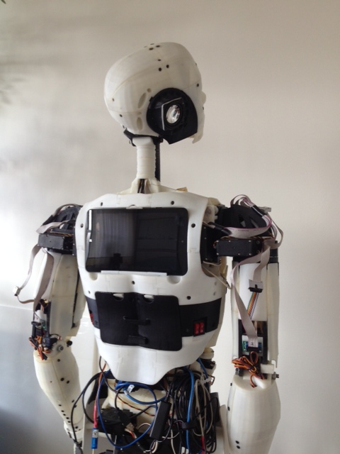
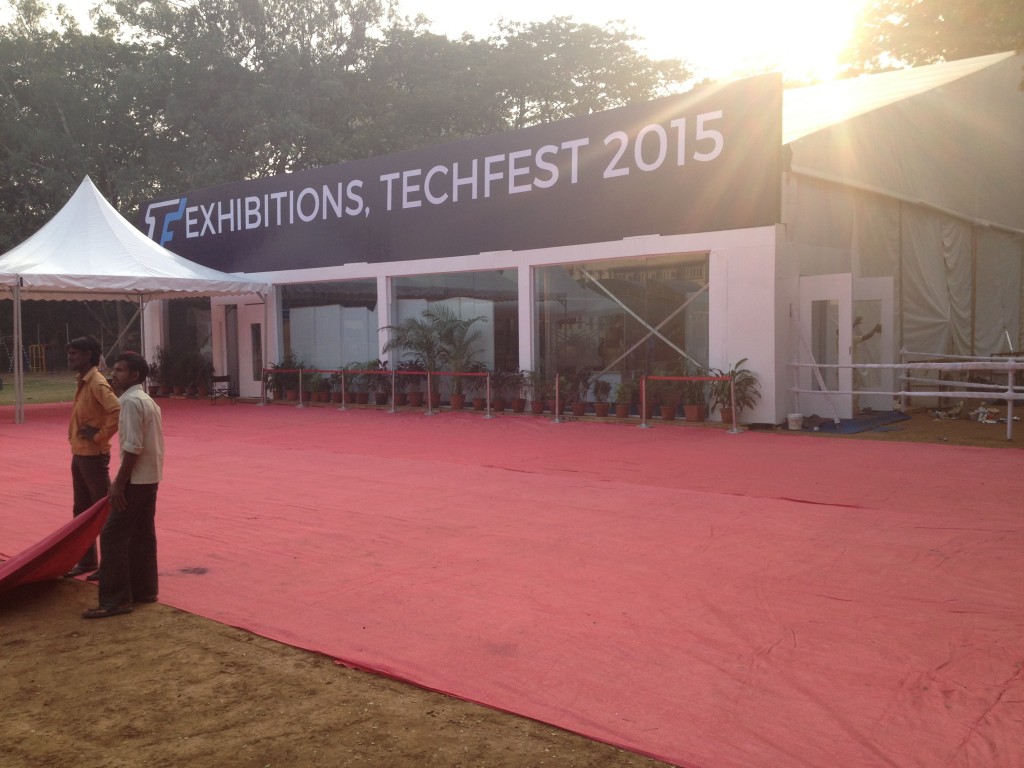
After the Tech Fest in India, one of the first things I had to do was to fix a hardware issue on the InMoov 2 hand. One of the drivers had burned out because the hand stayed powered with the thumb stucked in a wrong position. The main reason was because a wire of the thumb got tangled inside the palm. I had to redesign the paths of that wire and re-print the parts.
A few days ago, I received the Myo Thalmic Armband sent by Yohan of the FabLab Rennes and
MHK(Bionico Nicolas Huchet).
It was like receiving a Christmas present.
Searching on the Net, I found a Arduino library that allows the Thalmic to communicate with the Arduino via the computer.
I went on testing it and wrote a script, which first allowed me to use it with the InMoov finger starter (see third video) doing 3 small movements. The advantage of the Thalmic is the ease of use and set up. Once calibrated, you can remove it from your arm and put it back on (in the same position) it automatically works again, no need for re-calibration.
The goal with the Thalmic was to be able to use it with the InMoov 2 hand. Ideally is to set various possible gestures. In fact the InMoov 2 has an onboard Arduino Nano that lets the user create any gesture desired and can be modified by just a plug and play USB connection to any Computer. The Thalmic uses Bluetooth to communicate, and as for today it cannot communicate directly with all Bluetooth devices of your choice, but it will and the plan is to have an onboard Bluetooth Arduino set in the hand to allow direct communication.
I have been able to test the Thalmic also on the bicep muscle, it is more difficult to calibrate but I have been able to reproduce 3 differents set of gestures pretty reliably. Although the arm gestures to activate the sensor have to be rather large, which is a inconvenient if you want only the fingers of the InMoov 2 hand to be triggered.
So this is huge progress!!! In the below video I'm using double taping fingers to "wake up" the Thalmic, but I can also do it without, which lets the hand constantly ready for any muscle activity.
What else happened this month:
Alessandro has borged into
MyRobotLab the
Read More.................................................................